

Electronics engineering services
Electronics engineering, from the broken board to the production run.
Five disciplines under one roof — component-level repair, equipment modification, reverse engineering, system integration with IoT and AI, and full-cycle board design ready for manufacturing. We work on the bench, on the floor, and in the field, and we document every decision we make.
The same signal travels through every discipline we practice.
A repaired board has to behave the way the original designer intended. A modified system has to remain serviceable by the next engineer. A reverse-engineered schematic has to be readable as if the OEM had delivered it. An integrated IoT layer has to survive five years of dust and vibration. A production-ready board has to build cleanly at the CM on the first run.
We do not chase the shiny end of each discipline. We chase the quiet middle — the part where the work actually has to function on Monday morning.
Electronic board repair, down to the component.
We do not swap boards. We trace the signal path with oscilloscope and logic analyzer, identify the failed stage, and replace only what failed — preserving the rest of the assembly and the factory calibration that came with it.
- R-01Component-level diagnosis — analog, digital, mixed-signal
- R-02SMD / BGA / QFN rework with hot-air and infrared stations
- R-03Oscilloscope, logic analyzer, and thermal camera tracing
- R-04Schematic reconstruction when documentation is missing
- R-05Functional and burn-in testing before return shipment
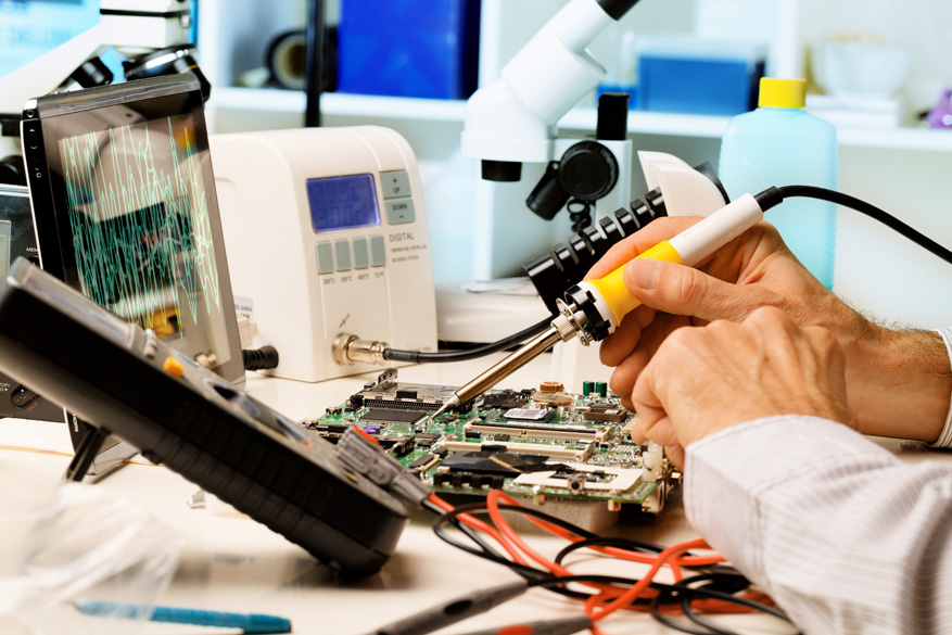
Where board-swapping ends, our work begins.
Most repair shops stop at the board boundary — identify the faulty card, order a replacement, ship it back. That works when the card is in production. It stops working the day the OEM discontinues it, the day the lead time stretches to 26 weeks, or the day the board is the only one of its kind on the continent.
We go further. Hot-air rework on 0402 passives, BGA reballing, vias repaired under the microscope, firmware recovered from a half-dead MCU. Every repair leaves with a written report: what failed, why, what was replaced, and what we would watch for next time.

Boards we will not pretend to fix.
A board that has been cooked by a switching regulator failure for six hours is rarely worth the labor to recover. A board with seventeen layers of blind vias and a confidential ASIC may be repairable in principle but not in practice. We will tell you that on day one, before the invoice starts, and we will tell you what the realistic path forward is — even if that path is replacement.
Equipment modification — hardware and firmware.
Equipment rarely dies all at once. More often it outlives its original intent — a controller that needs a new operating mode, a sensor chain that should talk Ethernet instead of RS-485, a firmware quirk nobody on the floor remembers the reason for. We modify the hardware, patch the firmware, and document the change.
- M-01Firmware patching, reverse-assembly, and re-flashing
- M-02Hardware retrofit for new operating modes
- M-03Sensor and actuator additions
- M-04Communication bus extensions (CAN, RS-485, Modbus, Ethernet)
- M-05Compliance re-certification support
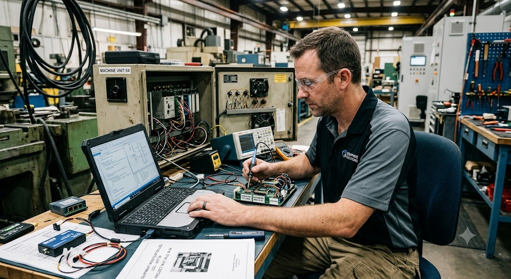
The equipment is fine. The requirement moved.
A packaging line that was specified for 40 units per minute now needs to do 60. A sterilization chamber that ran on a proprietary protocol now has to integrate with a modern SCADA. A pump controller that used to start on a contactor now has to ramp on a VFD. The steel is good. The motors are good. The board was built for a world that no longer exists.
We sit with the operators, map the new requirement, and modify — sometimes a daughterboard that taps the existing bus, sometimes a firmware patch that adds the mode, sometimes a full controller swap with the old I/O preserved. The deliverable is equipment that does the new thing, with a one-page modifier plate on the cabinet explaining what was changed.
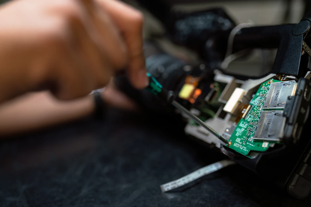
The rollback rule.
Every modification we ship is reversible. The original firmware image is archived. The original hardware state is photographed and documented. If a modification misbehaves in the field — and sometimes they do — we can return the equipment to its pre-modification state within a single service window. No mystery jumpers, no cut traces we cannot restore, no "you had to be there" explanations.
Reverse engineering — when the schematic is gone.
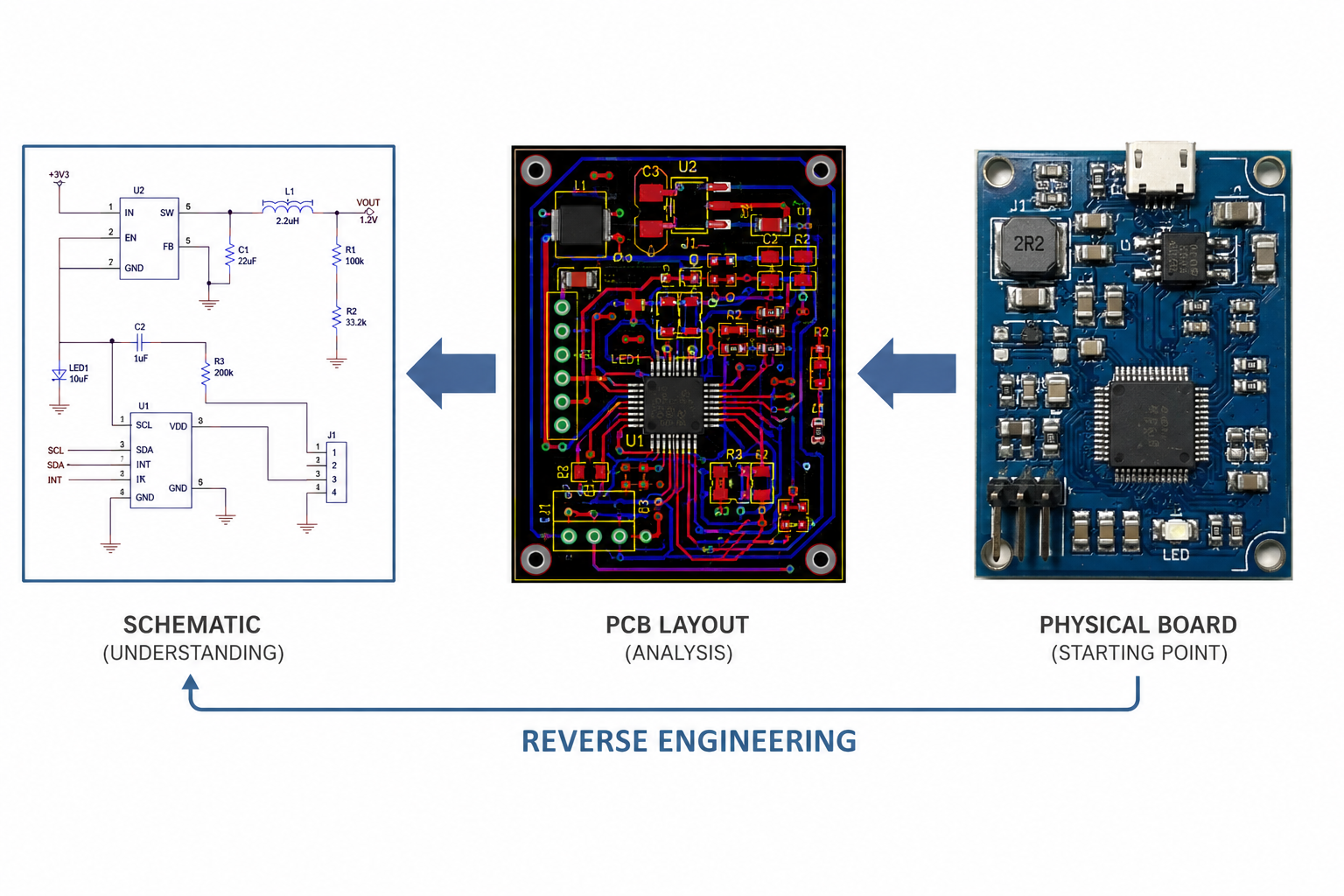
When the OEM is gone, the documentation is lost, and the board must be reproduced or repaired with confidence, we reconstruct it. Layer-by-layer scanning, netlist extraction, BOM identification, and a clean schematic delivered as if the original designer had handed it over.
- V-01Layer-by-layer PCB scanning and stitching
- V-02Netlist extraction from copper artwork
- V-03Component identification and BOM reconstruction
- V-04Schematic redrawn in Altium / KiCad
- V-05Verification: netlist diff against the physical board

Not a photograph. A schematic.
Scanning the board is the easy part. The work is in turning copper into a netlist, and a netlist into a schematic that reads like the original designer drew it — with the same functional grouping, the same signal flow, the same naming conventions. A schematic that another engineer can actually work from.
We have reversed 2-layer consumer boards, 8-layer industrial controllers, and 12-layer mixed-signal instruments. Each delivered schematic is verified by netlist diff against the physical board: every net checked, every component cross-referenced, every passive value measured under the microscope. If the diff is not clean, the schematic does not ship.

When reverse is not the answer.
Not every board should be reversed. A modern ASIC-heavy board with encrypted bitstreams, a board whose value is in the firmware rather than the hardware, or a board where the original BOM contains end-of-life parts that cannot be sourced — these are cases where reproduction is more expensive and more risky than redesign. We will tell you which case you are in before we start.
System integration — adding IoT and AI where it earns its keep.
Older equipment was not born connected. We add the missing layer — a microcontroller or SoC that reads existing signals, a wireless radio that ships the data off-board, and where it genuinely improves the operation, an edge AI model that turns telemetry into decisions.
- I-01Microcontroller and SoC selection per power and budget
- I-02Wireless: LoRa, BLE, Wi-Fi, NB-IoT, LTE-M
- I-03Edge AI inference — TinyML, TFLite Micro, custom kernels
- I-04Cloud telemetry pipelines — MQTT, InfluxDB, Grafana
- I-05Predictive maintenance models — vibration, current, thermal

Connectivity is the easy part. The hard part is the data.
Shipping a temperature reading to a dashboard is a weekend project. Shipping the right temperature reading, at the right sample rate, with the right buffering when the link drops, with the right battery budget for a five-year deployment, with the right security on the device and the right access control on the cloud — that is engineering.
We design the integration around the data, not the radio. First: what decision does the operator need to make, and what signal is required to make it. Second: what is the minimum sample rate and minimum latency that supports the decision. Third: what radio, what power source, what enclosure, what cloud. In that order.

Where AI belongs, and where it does not.
We will not put a neural network on a board where a threshold and a timer will do the job. We will put one on a board where the signal is genuinely complex — bearing fault signatures across a vibration spectrum, current waveform anomalies on a motor with variable load, thermal transient patterns in a multi-zone oven. The model has to earn its inference watts every time. If it does not, we ship the simpler version and tell you why.
Full electronics engineering — study to production.
From a one-paragraph requirement to a production-ready board. Architecture, schematic capture, PCB layout in Altium or KiCad, DFM and DFA review with the contract manufacturer, prototype bring-up on the bench, pre-compliance testing, and a documentation package the CM can build from without calling you.
- E-01Requirements engineering and architecture
- E-02Schematic capture in Altium Designer or KiCad
- E-03PCB layout — high-speed, mixed-signal, RF-aware
- E-04DFM / DFA review with the CM, before fabrication
- E-05Prototype bring-up, pre-compliance, pilot production handoff

Begin with the requirement, not the part.
The first deliverable is not a schematic. It is a one-page architecture document — what the board does, what it talks to, what its environmental envelope is, what its cost ceiling is, what its expected lifetime is, and what the qualification path looks like. That page is the contract. The schematic is the consequence.
From there: schematic capture with disciplined net naming, component selection biased toward parts with multi-source alternatives, PCB layout with stackup designed for the signal classes on the board, and a DFM review with the actual CM who will build it — not a generic checklist, the specific line that will run the job.
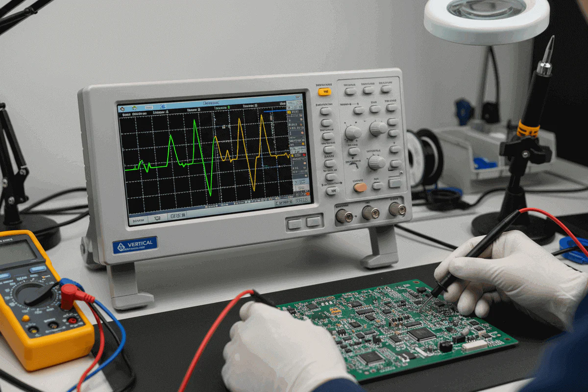
The deliverable is the package, not the board.
A board that works on the bench is not the deliverable. The deliverable is the fabrication files, the assembly files, the BOM with two sources per critical part, the test procedure the CM will run on every unit, the mechanical drawing for the enclosure, the qualification report, and the engineering logbook that explains every non-obvious decision we made. A package that lets the CM build 1,000 units without us in the room, and lets you maintain the product for the next seven years without us in the room either.
How a project actually moves through the lab.
Every engagement — repair, modification, reverse, integration, or full design — passes through the same six gates. The gates are not ceremonial. A project that has not cleared gate 03 does not begin schematic work. A project that has not cleared gate 05 does not ship.
Tell us what the equipment should be doing.
Send a paragraph, a photo, a schematic, or just a phone call describing the problem. We will tell you within a working day which discipline it falls under, whether we are the right lab for it, and what the realistic next step looks like. If we are not the right lab, we will tell you that too.
Start a brief →
Leave a Reply